![[Fast-Drying Pet Feeding Mat] Splash-Proof, Absorbent, Easy to Cl...](https://m.media-amazon.com/images/I/41Lj5J43BgL._AC_.jpg)


Testing Equipment Suppliers in the UK
1. TEquipment.NET
A leading supplier of electronic testing and measurement equipment, offering a wide range of products including oscilloscopes, multimeters, and signal generators.
2. RS Components
A global distributor providing an extensive selection of testing and measurement tools suitable for various industries, including electronics, electrical, and mechanical testing.
3. Farnell
Specializes in electronic components and test equipment, serving engineers and technicians with high-quality instruments for precise measurements.
4. Test Equipment UK
Dedicated to supplying specialized testing equipment for electrical, environmental, and industrial applications, with a focus on quality and reliability.
5. Hameg Instruments UK
Offers a comprehensive range of laboratory test and measurement instruments, including oscilloscopes, power supplies, and signal analyzers.
6. Keysight Technologies
A prominent provider of advanced electronic measurement solutions, including network analyzers, oscilloscopes, and spectrum analyzers.
7. Fluke UK
Known for durable and accurate electrical testing tools such as multimeters, clamp meters, and thermal imagers suitable for professional use.
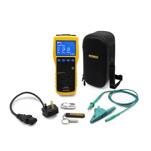
8. Megger UK
Specializes in electrical test equipment designed for insulation resistance testing, circuit breaker analysis, and cable testing.
9. Chauvin Arnoux UK
Provides a broad spectrum of electrical measurement instruments tailored for industrial maintenance, energy management, and research applications.
10. AEMC Instruments UK
Offers a variety of electrical testers including power quality analyzers, clamp meters, and resistance testers suitable for both fieldwork and laboratory environments.

Introduction to Testing Equipment
Testing equipment encompasses a broad range of devices and tools utilized across various industries to assess the quality, safety, and operational efficiency of products and systems. In essence, testing equipment plays a crucial role in verifying that materials, components, and finished goods meet the required industry standards and regulations. As sectors such as manufacturing, healthcare, construction, and electronics continue to evolve, the demand for reliable testing equipment becomes even more significant.
The importance of testing equipment cannot be overstated. In the manufacturing sector, for example, precision and accuracy in product specifications are paramount. Testing instruments are employed to check tolerances and ensure that the final output is consistent with predetermined criteria. In the healthcare industry, testing equipment is vital for diagnostics, enabling medical professionals to deliver effective treatments based on accurate assessments of patient conditions. Furthermore, construction and civil engineering sectors utilize testing devices to ensure materials can withstand necessary load and environmental stresses, which is critical for safety and durability.
In addition to these applications, testing equipment also serves as a fundamental element of compliance with industry standards. Regular testing and validation ensure that products adhere to statutory requirements, thereby mitigating risks and enhancing consumer confidence. The UK market offers a diverse selection of testing equipment suitable for various applications, ranging from simple handheld devices for basic measurements to complex automated systems for high-volume testing scenarios. This variety ensures that organizations can find the appropriate testing apparatus tailored to their specific needs, enabling them to maintain quality and operational efficiency.
Types of Testing Equipment
In numerous industries, an array of testing equipment serves critical functions, ensuring that products and materials meet established standards of quality and safety. The classification of testing equipment can be broadly categorized into mechanical testing equipment, electrical testing devices, electronic test instruments, and specialized test kits, each designed for specific applications across various sectors.
Mechanical testing equipment is primarily utilized for evaluating the physical properties of materials. This category includes devices such as tensile testers, which measure the force required to pull materials apart, and hardness testers, which assess a material’s resistance to deformation. Industries such as manufacturing and construction commonly employ this equipment to ensure materials meet the necessary specifications and regulations.
Electrical testing devices focus on measuring and analyzing electrical parameters. Common examples include multimeters, which assess voltage, current, and resistance, and oscilloscopes, which visualize electrical signals. These devices are essential in sectors such as electronics manufacturing and electrical engineering, where precise measurements are vital for performance and safety compliance.
Electronic test instruments encompass a range of tools designed to evaluate electronic components and systems. This includes spectrum analyzers, which examine the frequency spectrum of signals, and network analyzers, used to analyze the behavior of electrical networks. Such instruments are indispensable in telecommunications, automotive, and aerospace industries, where rigorous testing of electronic systems is crucial for operational integrity.
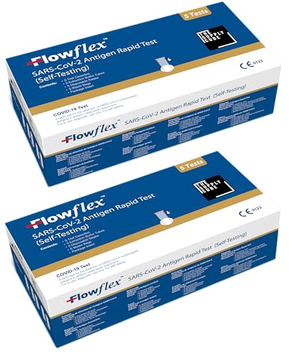
Lastly, specialized test kits cater to specific testing needs, often addressing niche markets. Examples include water quality testing kits, commonly utilized in environmental monitoring, and diagnostic test kits used in healthcare settings for rapid analysis of biological samples. Overall, the diversity of testing equipment available in the United Kingdom reflects the varied requirements across different sectors, ensuring that quality assurance is maintained at every level of production and service delivery.
Notable Manufacturers and Suppliers in the UK
When it comes to testing equipment in the United Kingdom, several manufacturers and suppliers stand out due to their established reputation, product offerings, and distinctive attributes that cater to diverse industry needs. Companies such as Fluke Corporation, Eleco Technology, and Testo are significant players in this sector, providing high-quality equipment and comprehensive support for their customers.
Fluke Corporation is renowned for its wide range of electronic test tools, including multimeters, thermal cameras, and power quality analyzers. Their products are highly regarded for precision and reliability, making them a preferred choice among professionals in various fields such as electrical, HVAC, and manufacturing. The company also focuses on innovation, which often results in new solutions that integrate advanced technology for enhanced performance.
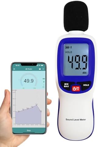
Eleco Technology specializes in environmental and engineering testing equipment, offering solutions geared towards construction and safety professionals. Their product lineup includes moisture meters, sound-level meters, and vibration analyzers, all designed to comply with industry standards. Eleco distinguishes itself by providing exceptional customer service and a strong emphasis on training and support, ensuring that clients can utilize their products effectively.
Testo is another leading supplier known for its portable measuring instruments, particularly for temperature and humidity monitoring. Founded on innovative engineering, Testo has a range of solutions suitable for the food industry, HVAC applications, and more. The user-friendly design of their equipment coupled with reliable data collection makes them a popular choice among end-users.
In selecting a supplier of testing equipment, customers should consider several factors, including product quality, customer service, and reliability. Establishing a strong relationship with a manufacturer or supplier is crucial, as ongoing support ensures that clients can effectively utilize the equipment and maximize their investment. With various options available, careful research can lead to a partnership that not only meets technological needs but also enhances operational efficiency.
Future Trends in Testing Equipment
The testing equipment sector in the United Kingdom is undergoing a significant transformation, driven by advancements in technology and changes in market demands. One of the predominant trends is the increasing integration of automation and digitalization in testing processes. Automated testing tools are designed to enhance efficiency, reduce human error, and provide real-time data analysis. This shift not only streamlines operations but also enables organizations to conduct more comprehensive tests with greater frequency and precision.
Moreover, the rise of the Internet of Things (IoT) has facilitated the development of smart testing equipment. These devices are capable of collecting vast amounts of data that can be processed and analyzed using advanced algorithms and machine learning techniques. As a result, testing equipment is becoming more intelligent, providing insights that were previously unattainable. Companies that embrace these innovations will be better positioned to improve quality assurance processes and meet customer demands more effectively.
Another key trend is the growing emphasis on sustainability in the testing equipment market. There is an increasing awareness of environmental impact, prompting manufacturers to design equipment with sustainable materials and energy-efficient operations. As regulations tighten around environmental practices, companies that prioritize sustainability in their testing equipment will gain a competitive edge. This not only fulfills corporate social responsibility commitments but also appeals to a consumer base that is increasingly concerned with environmental issues.
As the market evolves, organizations must stay agile and adaptable to remain competitive. By investing in new testing technologies and aligning with emerging trends such as automation and sustainability, companies can ensure that their equipment meets both current and future demands. Embracing these trends will likely provide significant opportunities for innovation and growth within the testing equipment sector in the United Kingdom.
Contact information — Please use contact form on http://www.abshot.com/contact/

